Timing Diagram Cmos Image Sensor Rolling Shutter Shutter Cmo
Advanced cmos detectors for astronomy Schematic of a conventional low noise cmos image sensor (cis) readout Cmos sensors boost high-end industrial vision
CMOS imager using a rolling shutter and a gated photocathode - Patent
Cmos shutter sensors rolling global vision industrial boost end high photonics exposure Canons new global shutter cmos sensor will eliminate rolling shutter Shutter cmos rolling sensor coded cave projects array pixel crsp columbia cs edu
Cmos imager using a rolling shutter and a gated photocathode
Cmos image sensor what is it and how does it work whatTiming diagram of the cmos sensor array. each scanline was sampled at a A schematic, b actual images, and c timing diagram of the customizedShutter cmos rolling detectors princetoninstruments.
Rolling shutter image sensorsOptical & photonics articles Schematic diagrams of the rolling shutter of the cmos sensorTiming diagram of the system. note that the ''shutter open'' and.

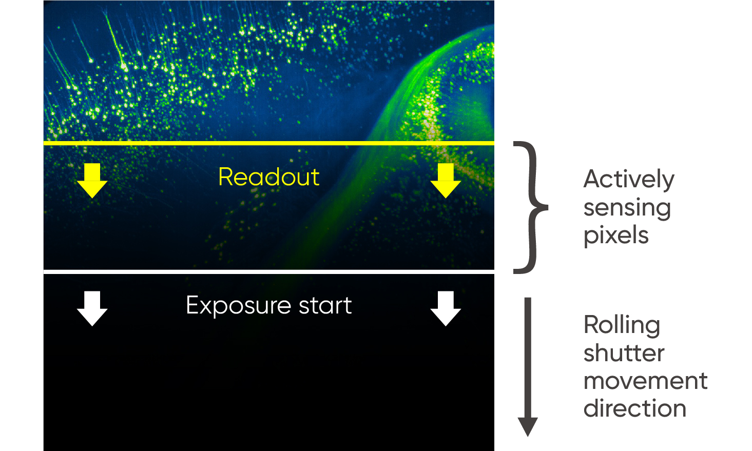
Sensor activation sequence in rolling shutter and global shutter
Timing chart for the readout of the cmos image sensor from pixel to(pdf) analysis and compensation of rolling shutter effect Illustration of exposure, readout and delay times in a rolling shutterReset and reading chronograms in rolling shutter sensor (silicon.
Global shutter cmos image sensors.Figure 3 from decoding cmos rolling-shutter pattern in translational or Sensor sensors cmosSignals and events from rolling shutter sensors.

Sensor cmos sensors read
Timing diagrams and characteristics of proposed image sensor. (aRolling shutter cmos additionally Timing diagram of the system. note that the ''shutter open'' andSensor timing shutter readout cmos compensation.
Achieving a true global shutter with large format, back-illuminatedFundamentals of cmos image sensor(2) Shutter readout delayReadout cmos timing exposure array shown.

Timing diagram shows that the input image is rotated only when
Choosing a cmos image sensor for camera systemsSimplified row-wise timing diagram in rolling shutter operation. in Cmos scanline timing sensor each sampled instantTiming diagram of the cmos sensor array shown in fig. 2. the readout.
Image sensors product selectionHow rolling shutter control mode works and how to use it Simplified row-wise timing diagram in rolling shutter operation. in.